


Building the W17 Main Hull — Part 1: Construction
Although all these steps are well covered by the Plans and Build Manual, running through them again with more pictures can often help, and perhaps introduce some new idea or tip since the Manual was written.
NOTE: The building of the W17 hull and amas is based on a relatively new method called the ABC-System that is even simpler than the Stitch and Glue from which it was developed. It saves time and eliminates all the wire holes that need drilling and filling. Read more about it here.
Panel preparation
Building the hull first assumes that you've already scarfed the side and bottom ply together to create panels of the correct length. Because these ply joints are wider than the table, you may chose to create them with an angle-grinder while all 4 panels are laid up together, with their datum lines all parallel to each other. Make sure that the forward panels are laid with the outside face down and that the aft panel is laid face up. Now set the edges back from each other by 50 mm—keeping them exactly parallel.
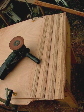
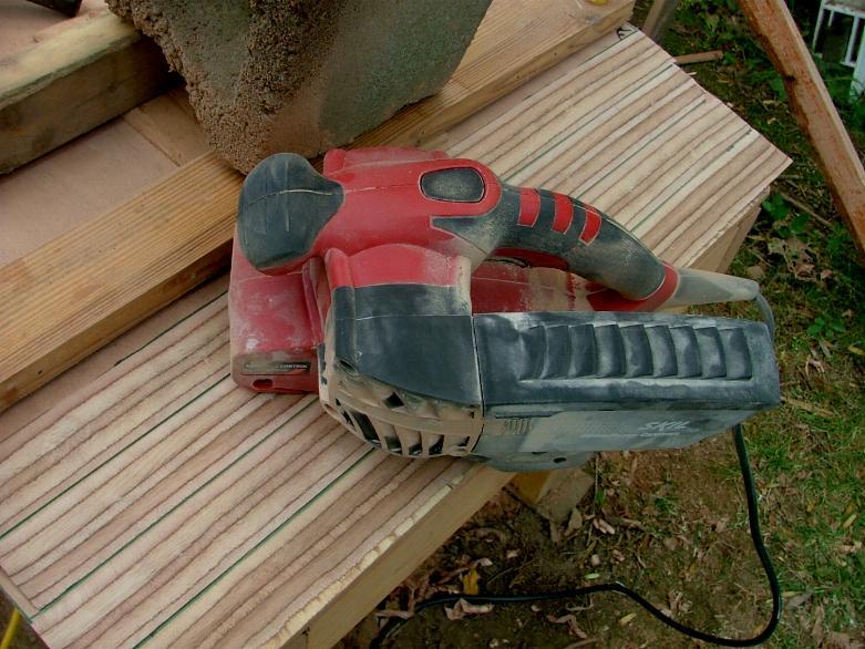
Clamp the panels down and after grinding off about 80% of the taper, you can complete the job either with a sharp hand plane or with a belt sander. (Incidentally, the dust collected in many belt sanders makes excellent 'wood flour' to give some color and thicken epoxy.)
Once joined and cleaned off flush, consider if you will epoxy coat or sheath the inside before it's installed. Do one or the other. I recommend to sheath if using 5mm or less, but epoxy coat will generally be adequate for 6mm ply sides. Also laminate up the main hull stem-piece from the four parts on the drawing.
Setting up the frames
First thing is to sand off the Building Platform and erase any previous markings used for the amas, being as the main hull frames will be differently located. Using the existing centerline is fine but make sure it's still straight. Also re-check the level of the platform in all planes and areas, as leveling wedges under the feet might have become displaced. (I suggest 'tacking' them in place with a hot-glue gun, once level.)
Starting at the bow, mark off the location for all the Stations—Station 10 back to Station 1—all 500 mm apart, starting with Station 10 at 125 mm aft of the front end of the platform, or whatever places the front edge of your stempiece at 190 mm forward of Stn 10.
Locate the forward bulkhead, aft of Station 7 as per plans and also the aft cockpit bulkhead, just forward of Station 1, also as per plan W17-02. Mark clear lines on the Build Platform—each perfectly square to the centerline.
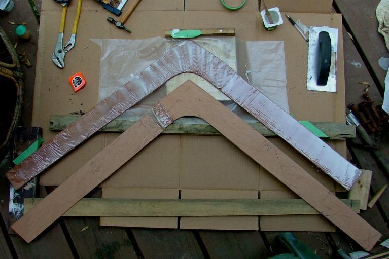
Check and make sure you have the 'dagger-board case center girder' all complete and that its forward end fits correctly into the slot in the forward bulkhead.
 Now locate four scraps of plywood about 300 mm × 100 mm. Plane one end square and then mark 'a deck line' on two of them at 156 mm from the square end. Now place these on the Forward Bhd with the line at the deck edge and push them as far outboard as possible without going closer than 10 mm to the sides. Now hot-glue these supports to the bulkheads with a few 20mm long tacks. These supports can now be well hot-glued to the Building Platform—making sure 1) they lie on the location line previously drawn, 2) that their centerline is vertically over the Platform centerline and 3) that the bulkhead is vertical to the platform top.
(Although it will not make a huge difference for this slim boat, the bulkheads Forward of amidships (Stn 5) should have their AFT face on the position defined and bulkheads AFT of amidships (Stn 5) should have their FWD face on the defined line. This rule is standard for most boats and allows for typical bulkhead edge bevel.)
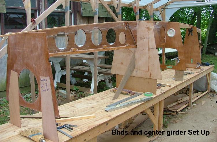
Now install the temporary frame at Station 5 (178 mm above the platform) and the aft cockpit bulkhead (180 mm above the platform)—following the same general method and precautions.
Once these are in place, you can drop in the dagger board case and girder assembly, with its after end butted against the aft bulkhead, 45 mm forward of Station 2. Temporarily clamp a piece of wood under the aft end of the centerline web to hold it up flush with the aft bulkhead.
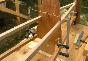
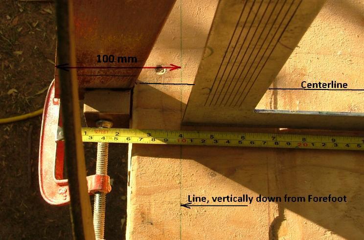
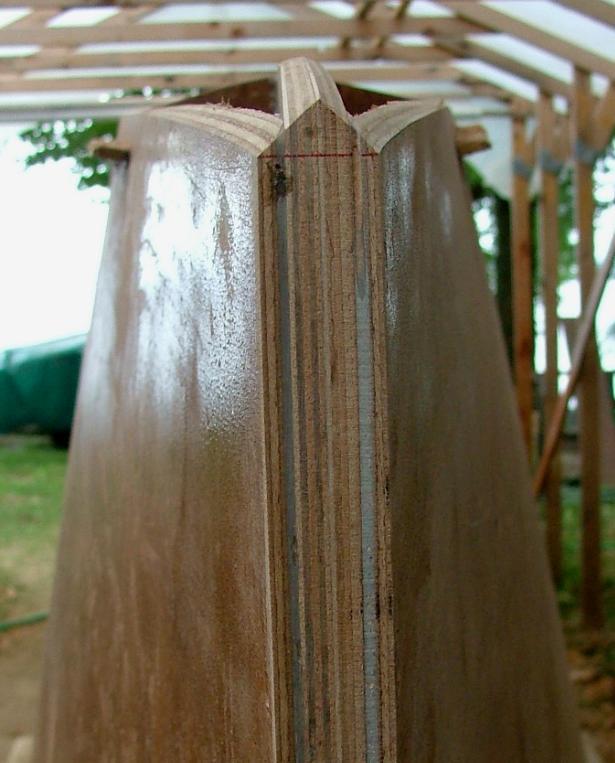
Once the transom is set up at the correct angle and height and the stempiece is attached at the platform, pass a batten from the stempiece to the transom to make sure all looks fair for the bottom ply. The rear edge of the stempiece, should fit against the platform and a block used to screw it there at the right height. Locate the front stem edge with approx 100 mm of rake—see photo.
The only thing that occasionally needs a slight adjustment could be the centerline girder. Once all is in line and the curve is fair, bond the aft end of the centerline web to the aft bulkhead, by chamfering off (beveling) the sides of the web, so that the joining epoxy can get almost to the centre of the web plywood—like a weld—which is really much more what a gap-filling cement like epoxy does.
Stringers
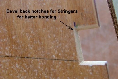
The next task is to fit the stringers (one each side), after first scarfing the timber to get nearly 17 ft (5 m) total length. The stringers are located vertically by a distance (given on the plans) from the Datum Waterline to their upper edge. The depth of the required slot will be to suit the wood stock you are using (20 mm on plan). Bevel back the edges of each slot as shown for better bonding.
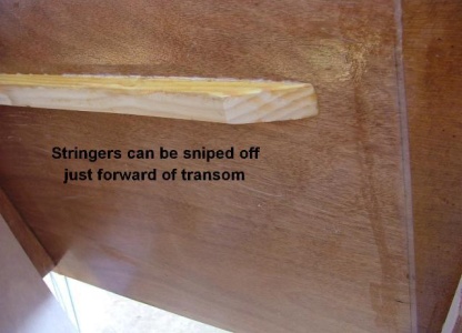
The aft end can be stopped 100 mm short and just sniped against the hull side to save weight and complications.
Sides
Before fitting the sides, it's best to drill a ¼" dia pilot hole through the center of the stempiece at the correct angle (see plan), for the eyebolt—while both sides of the stem are still visible.
This will later be drilled out to 5⁄16" (8mm) for the eyebolt that supports the bowsprit and will also be used for the trailer.
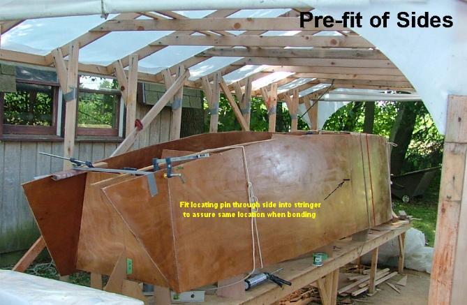
First make a preliminary fit of the side panels, after grinding the reinforcing pads on the stem, flush with the stringers. Once they are well fitting to all frames and stem, drill a 6mm (¼") hole into the stringer, close to the center of the panel. This is to fit a locating pin to guide the final installation back into this same position, once stringers and bulkheads have epoxy applied to them.
Mark where the side panels will touch the stringers and frames, so that area can be lightly sanded before bonding.
Then remove the panels, sand the future contact area and apply thickened epoxy to the stringer and bulkhead edges. Ideally with a helper, reposition the side panel over the locating pin, avoiding to contact the epoxy until it's in the correct position.
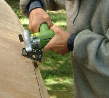
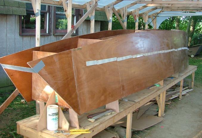 Then, after checking that the bow also fits properly, hold a stapler FIRMLY against the ply side and punch staples through into the stringer, working from amidship towards the ends, driving the staples (14mm) over or through something like a small cable, plastic or cardboard strips, to permit easy removal of the staples after the epoxy has cured. Use duct tape to pull the ply ends together to make good contact with the stem and transom.
 Once cured, remove the staples and mark where the bottom of each bulkhead comes on the side ply and draw a fair line through these points. Cut just above this line with a small saw. Then spring a batten around that edge, about 50 mm below what will be the bottom joint. Clamp closely to the ply to create a fair edge. Attach this with many 30mm lengths of hot glue. This will stiffen the edge temporarily, until the bottom is on.
It's worth noting here that with the ABC System, the only joint that is fully completed while the boat is being built upside-down, is the underside of any stringer .., as this will be on top and accessible while building upside down. All the other inside joints are coved and finished only AFTER turning the boat over, when they are far more accessible. Prior to that, the boat is really only 'tack-welded' together with epoxy, so needs to be rotated with some care. ;)
Bottom
Plane the side edges flush with the bottom of the bulkheads. It's best to grind or sand the corners of the lower bulkhead edge as per sketch. This will  permit the final fillet to grip the bulkhead stronger. Sanding the inner edge of the side ply will permit the same at the joint for the bottom. Also bevel the inner corner of the daggerboard case for the same reason. Using a straight but flexible batten, check that the centergirder and DB case, lays fair with the bulkheads.
Then fit the bottom panel after first having sheathed its interior for added strength and better resistance against any future bilge water penetration.
Cut the bottom panel back from the stem along the centerline, about 1200 mm from the forward end. This will permit the bottom panel to take a slight vee-shape up forward.
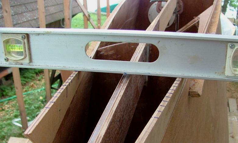 In order to vee the two sides the same, it's a good idea to make two identical wedges with depth markings, and then check with a level (assuming the boat and platform were level in the first place)—see photo.
You may need to wet the bottom ply surface up forward, to give it the twist it needs—up to about 45°—right at the bow. (See plans and photos.)
 Use ropes and plywood wedges to get the contact you need. Leaving the moist twisted panel in place overnight, will make final fitting much easier the next day.
Also cut out the final aerofoil opening for the daggerboard. This will give enough access to form an inside epoxy fillet with your small finger. The rest will be done later, once the boat is turned up the right way.
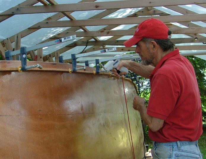
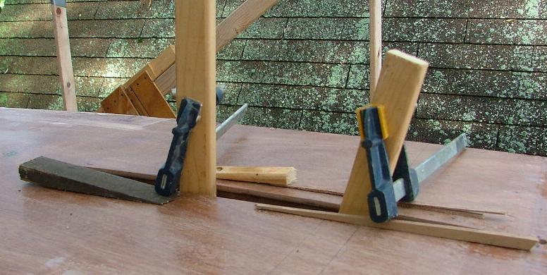 Once happy with the fit, apply thickened epoxy to the thin ply edges and hold down to the sides with many transverse strips of duct tape. As long as contact is made and maintained, this will be enough for now. The joint strength will come later from external taping plus inside fillets and more tape. In way of the daggerboard case, use a couple of lengths of wood through the case slot and wedge the bottom to the case as shown. I'd recommend to use a high density/strength filler for this bonding mix—such as West System #404.
Taping and sheathing
 Once cured, sand the external corner with a 300mm long sanding block so make as fair a line longitudinally as possible. Do not round off too much (not more than 4–5mm rad) or you will cut right through the joint. Pre-coat the corner area with a saturation coat of epoxy. If using a fairly viscous epoxy like WEST System, adding up to 5% acetone to this first saturation coat will help penetration, but allow it to evaporate before overcoating.
Once hard, lightly sand again and add 40–50mm wide 300gm tape to the exterior corner.
If any part of the joint tape does not want to stay close to the ply, add a piece of kitchen wax paper over it and then tape that down with masking tape until cured. Coat the complete ply surface with one coat of epoxy.
Then clean off the side ply at the stem and fit the false stem.
Once all is cured, lightly sand again and oversheath the bottom with your choice of glass or Kevlar®. (See note below for use of Kevlar®.)
Once cured, lightly sand again and fill with a light mixture of epoxy and microballoons or microspheres, and use a squeegee (plastic spreader) to obtain a smooth, fair surface.
Typically one will need to sand and apply two further thin coats of this surfacing mix, in order to obtain a decent, fair finish.
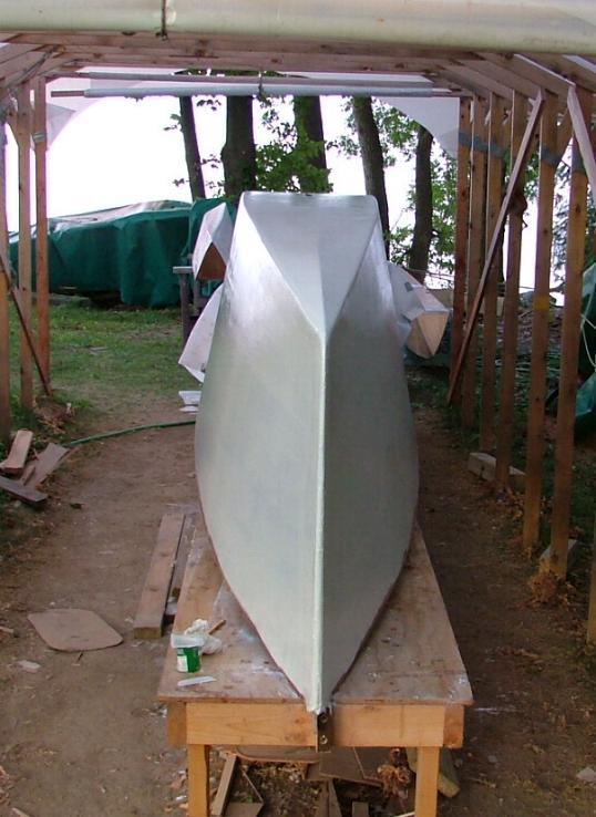
Once there, you may decide to paint before turning the hull over. Apply two coats of 2-part epoxy primer, followed by two coats of polyurethane finish—lightly sanding with wet paper between each coat. See Part 2 for more on painting.
Use of Kevlar®
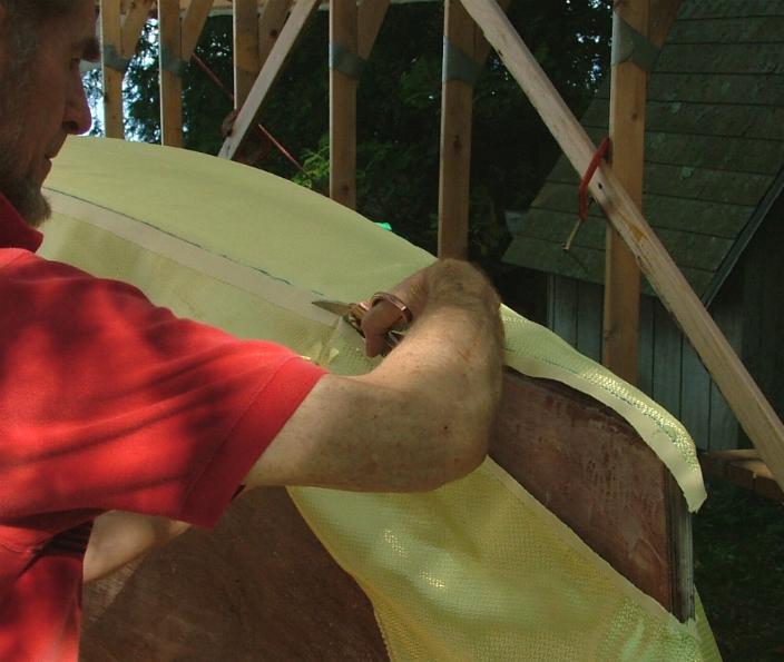 If using Kevlar®, you'll also need to oversheath with a light glass, as Kevlar is virtually impossible to sand without creating woolly fluff. Again, use wax paper and taping to hold down anything that is difficult. Cutting Kevlar is also notoriously difficult but here is a way I've found to 'tame the beast'. Stick masking tape over the area you plan to cut and mark your cut line on that. A good pair of ordinary steel scissors will then cut it without much difficulty. Leave the tape on the top surface when bonding the edge down. With epoxy brushed on the ply under it, tape the edge down with another length of masking tape. The epoxy will soak through to the masking tape and once cured, you'll be able to remove the tape and the edge will be well attached. (Do not brush epoxy on the Kevlar under the tape, or the tape will come unstuck.) Then oversheath with glass and hold that edge down with strips of wax paper and more temporary tape.
See Main Hull — Part 2: Painting
See Main Hull — Part 3: Interior
See Main Hull — Part 4: Beams & Cockpit
Read more Construction Tips & Techniques.
"New articles, comments and references will be added periodically as new questions are answered and other info comes in relative to this subject, so you're invited to revisit and participate." —webmaster
"See the Copyright Information & Legal Disclaimer page for copyright info and use of ANY part of this text or article"