


Intro Part 1—The W17 'Estuary' Trimaran
For additional descriptive information on the W17, CLICK on one of the links below.Preliminary Design Concept & Development
Review of W17 Hull Forms
Intro Part 2—Building the W17
Intro Part 3—Build Manual & Plans
W17 Study Profile
Order Plans
I am pleased to announce that the detail building plans for the new W17 are now ready. If you're not familiar with this new design, rather than repeat myself, may I first suggest you read its initial introduction on this site, W17 Trimaran Design, and then continue back here.
One thing that IS worth repeating here are the main design goals for the W17; because if a new owner is to be happy with this boat, he or she first needs to feel in tune with the specifically planned attributes.
So these were to be:
- speed, sailing efficiency with a light, responsive helm
- comfort
- relative dryness
- ease of handling, both sailing and ashore, along with a
- relatively small budget and
- reasonably short build time by almost anyone with basic woodworking skills whilst using…
- readily available materials
- the boat should be easy to prepare for trailering and finally ....
- look unique and attractive, and offer a number of features not found on competing craft
To achieve the above, this unique design has incorporated some interesting new ideas and I am sure the boat will not only be exciting to sail and own, but also be an eyecatcher that will be a constant conversation piece. (As you read this, keep in mind that it was written in 2010 when the boat was first conceived).
In Part 1 of this article about the W17, I will elaborate principally on design aspects and choices, but follow that up with Parts 2 & 3, first giving a brief rundown of the proposed building procedure and then in Part 3, explain what the plans show and provide a detailed list.
By that time, the detailed Building Manual should be complete and the plans will be up for sale, so it's time to start thinking seriously about this fun boat.
I've intentionally numbered the main design targets above as I will insert these numbers in the appropriate places while I describe the design to you in more detail below, so you can readily see what aspects help to satisfy what target.
The 16 sheets of plans are well detailed and I will give each buyer an email address to reach me quickly and plan to get a reply back on most questions within 24 hours. The plans come with a very detailed written account of how to assemble the parts and give lots of tips along the way on what order to do thing and why, and also how to generally proceed for the best results (6).
Let me first run through some of the unique features of the boat itself. The main hull has a very simple but surprisingly effective hull shape that being quite slender, will slip through the water with minimum fuss. (1,3,5,6). A much smaller 12-footer served as a test bed for this shape and worked better than expected. The secret is to keep the flat bottom forward, fairly deep under the water surface. For this main hull, both 4 and 6 mm marine plywood is specified. This hull has a central web in way of the cockpit and this includes a box that houses the rather unique 'pivoting dagger board'—more on this later (1). The flat bottom is also easy to accommodate on either a beach or on a simple inexpensive flat bed trailer (4,5,6,8). The amas are also easily made of narrow panels of plywood that only require one scarf per panel. Even for the scarfing, clear, simple directions are given to take all the potential worry out of this task and once you've seen how easy it is, you'll probably give up butt joints forever. The amas are unique in that they are slightly asymmetrical. This was done to reduce impact with wave tops (3), add significantly to low leeway while still maintaining a form that's easy to drive (1), be quick to build (6) and look attractive (9). Both the amas and the main hull can be built very quickly using basic tools and readily available material, using the simple building platform that is detailed on the plans (5,6,7)
The akas (cross beams) are composed of 3 units—a straight, central box section that will be permanently bolted and bonded to the main hull deck, along with 2 contoured beam ends that will be permanently bolted and bonded to the amas. While the curved beam ends are perhaps the most challenging part of the whole boat to construct, they are well detailed with step by step instructions in the building procedure and not difficult. They are also well worth the effort as they raise the crossarm above most wave tops and also remove any tendency for the boat to look boxy (1,3,9).
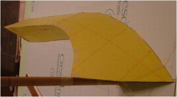 Although optional, it is highly recommended that the forward beam also be fitted with fairing panels to avoid wavetops crashing into a flat front. so creating an excess of spray. Full details are provided in the plans and the proposed design will further add to the unique look of this boat. Here is a mock up of the outer fairing and the plans include full development of the required panel shapes
The folding system is created by the use of heavy stainless hinges with removable lower pins and these hinges are well detailed with special installation tips and even a suggested supplier (4,8). The forward fairing will stay in place permanently and not be affected by the folding system.
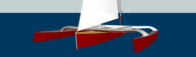
As the forward beam carries at least 2⁄3 of the ama load, it is built heavier than the aft one, though the shape of the outer contoured part is similar for both. To get an overall idea of how this (and the whole boat) will look (2010), here is my rendition of a W17 against the real water of beautiful Lake Champlain in upstate Vermont, USA.
 There are a number of important features that are not so clear on this image, so I will try to describe them.
One key aspect of this design is the raised cockpit floor that not only provides support for a pivoting dagger board but also allows the cockpit to drain continually back to the sea, for comfort, safety and lightness—assuring good speed is maintained (1,2,3,4). The pivoting dagger board is a concept I developed for a Div ll sailboard, after finding it difficult to tack back home against a head wind, with the water becoming less and less deep. There is no doubt in my mind that a sporty boat like this can really benefit from a dagger board compared to a conventional pivoting center-board, as the latter inevitably needs a long slot that adds much resistance. But straight dagger boards are hazardous to use over shallow, rocky bottoms, even when fitted with crash boxes, as these still only permit a small movement.
As for my Div ll board, I needed more than a few millimeters. So I made the dagger board slightly narrower than the case and also angled the upper part (see plans), so that in the case in the W17, the lower tip can now be readily pushed back significantly, reducing draft by about 300 mm (12") on impact and by then, present a very gentle angle to bottom obstacles, over which it will typically ride without effort. After some initial impact is felt, it will also be easy to manually retract the dagger board 'up and forward', still allowing enough control for tacking. It's simple and effective (1,4,9) and also permits the dagger board to be made quite independent of the boat and therefore by alternative methods & materials, several of which are noted on the plans.
Particular attention has been given for cockpit comfort while sailing. In my opinion there is no reason to have to sail with your back all twisted (as happens when perched on some unforgivably sloped cockpit rails I've experienced) … or even with a gunwale rail cutting into your back. There are none of these on the W17 as even the gunwale has been moved to the outside of the main hull except at the extreme bow (2). There will in fact be 4 different places to get comfortable on this relatively small boat. If you're not too big or inflexible, there is the cockpit floor itself—one of my favorite places in light weather. Then there is the main seat at the side of the cockpit plus a raised and comfortably wide horizontal cockpit rail and finally, the outboard optional trampoline area, which incidentally is also wide enough to do an overnight in a small tent. (2,9).
The rudder arrangement is another unique feature of this boat and the basics of this were taken from a kayak I own that also uses a horizontal deck-level top hinge … something also featured on the little 12-footer that I was able to test sail during the summer of 2009. What I like about this arrangement is not only its light weight and solid feel, but also the way the partially balanced spade rudder gives a nice light helm with a relatively small rudder that takes less draft. It can still pivot up as one comes ashore and can be arranged to release on contact to avoid damage.
The mainsheet was a problem on the small boat unless the boom was nearly amidships, so after not finding anything better, I have elected to go with a long curved track that will certainly avoid repeating similar issues. Strong Hi-Beam tracks are available already curved from several suppliers and although not inexpensive, will make the boat much safer and more pleasurable to sail, so for me, it's money well directed and spent. Being as this system is more generally used for large professional raceboats, it also adds a nice touch of efficiency and performance to its appearance (1,4,9). I would also recommend the use of a mainsheet quick-release cleat (such as the relatively recent Spinlock series). Because this cleat cleverly permits the release under full load, it allows the experienced sailor to leave the mainsheet cleated far more than would normally be recommended, adding to the comfort and ease of sailing the boat (2,4,9).
Two other unique features of this versatile and fun boat, involve its rig. This boat is of a size that can readily use sails from a small beach catamaran of say 17-18'—though preferably of at least 5-oz material. In some cases the mainsail peak may need cutting down to fit the slightly shorter wingmast but this is readily done at fairly low cost by most sailmakers. Whatever the upwind rig chosen, the boat has been planned from the start to carry an additional drifter or asymmetrical spi on broad reaches to supplement the loss of apparent wind when sailing off wind. In order to not interfere with the jib that will likely be set on a roller, the jib tack has not only been moved 300 mm aft but there will also be a small bowsprit to ensure good separation between the foresails. Again with a unique appearance, this sprit will not be round as is common, but flat topped and wide, as this design will only need a bobstay and no lateral support.
The short sprit will readily socket into a sleeve above the deck, keeping the boat as compact as possible when ashore.
The final 'pièce de résistance' that will appeal to many and for good reason, is the inclusion of a unique wing mast design for this small boat. Although some extreme and unrealistic claims have been made for the improvement in performance that a wing mast can give, I am confident that this design will give at least 10% more lift and that's an important boost. As many find it hard to find reliable, usable information for such a mast that can be built in a home shop, I have decided to include plans for such a design for those who are really serious about building this boat. This design will also not require special skills or facilities that are beyond the average good boatbuilder and that will cover most of you out there considering this design. Even generic wing mast plans are typically sold for around $200—which is more than the complete set of plans for the W17, and because of that will only be sent out after the designer sees pictures of your W17 hulls nearing completion. It's the bonus for getting another W17 on the water and sharing your pics for others to see and enjoy ;-) I actually have two Waters Wing Mast designs, with the wood one best suiting the Cruise Rig and eventually coming FREE with the boat plans. The second design is of carbon fiber and after testing, will be the mast for the Race Rig. With time, I hope to dispel some of the mysteries of wing mast design and show that if sound engineering is applied within a good design process, and if good materials are properly considered and used, then a reliable and attractive wing mast is within reach of a lot more sailors than would appear at present, and for a material cost that are certainly less than a standard alloy spar. Both cruise and race designs have the option of being primarily built with carbon fiber for greater stiffness and some weight saving, but the cruise rig will also have the less expensive option of being built using fiberglass and suitable wood.
So that's the overall view of the W17 design and I hope you will agree with me that the general goals of the design have been effectively achieved.
Click here for Intro Part 2—BUILDING the W17.
Click here for Intro Part 3—Build Manual and Plans.
Click here for Study Profile.
Enjoy !… and feel free to send in specific questions via my Questions Form, that I may select to answer through this webpage if considered of broad interest.
"See the Copyright Information & Legal Disclaimer page for copyright info and use of ANY part of this text or article"