

W22 Build INDEX
Building the W22—Article #3
Cross Beams
With the amas now finished, let's step back and look at how one might create the cross beams in carbon fiber (or even fiberglass) instead of purchasing beams of extruded aluminum. I chose mast section beams for the W22 as they not only look much better, they also require a lower socket profile to fit them to the main hull and the ama. In addition, they create less water disturbance, so the boat stays drier.
So I'm not personally a fan of round tubes for trimarans although they are a frequent choice. If one enquires around at various large marinas, one can often find masts that have failed (typically due to a rigging failure), but short sections of it can still be straight and this is all that is needed for the W22. The design even allows for a possible joint on the centerline of the aft beam that could also have a slightly smaller section for the aft beam making each side just under 9 ft (2.74 m) in length and the forward beam halves will be even shorter as they fit into reinforced gunwale boxes to keep the cuddy more open.
But if we really want to reduce weight of this relatively heavy part and stay consistent with the much preferred aerofoil section, then we should look at building this in carbon fiber.
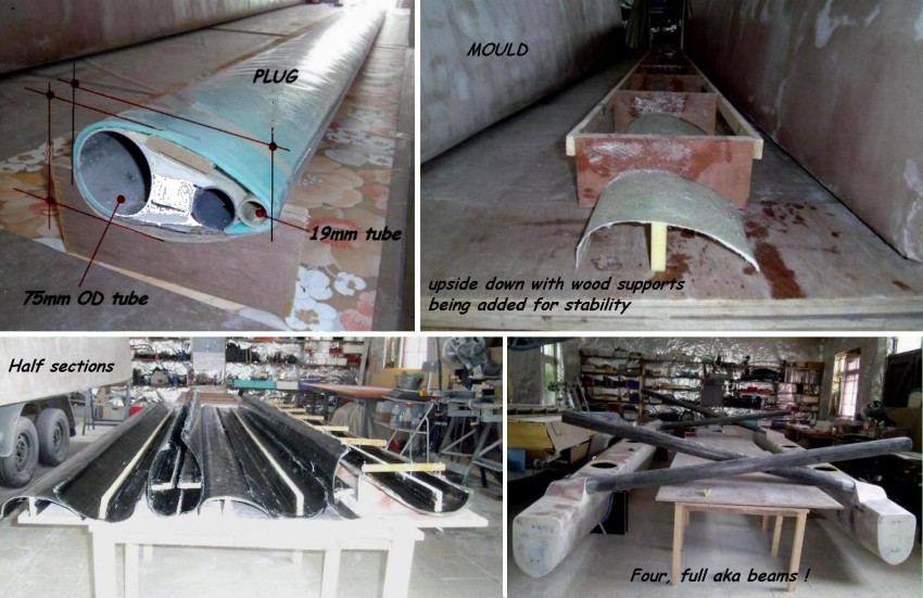
If this were a one-off beam, I would have another approach, as I do for making a one-off CF mast. But in this case, we need four ½ length beams, so it's worth thinking about a mould. In fact, if we build this with a top and bottom half, there will be 8 identical pieces, so a mould is the way to go.
The Manual therefore explains how to build up a realistic section and then create a mould from one side of it. This is then 'doctored up' to be smooth and well finished, so that 8 half-sections can be created within it. The plans suggest a way to create a small mating flange for the two halves, but this builder chose to add extra foam inside at the joint and leave off the flange. Although it worked fine, I think the flange does add something. It ensures that the mating moulded edge stays straight and should therefore facilitate the joining.
Here are some pics of the various stages.

(In the case shown, the forward akas are longer than they will need to be, as they were built prior to the decision to fit the gunwale boxes.)
Main Hull Preparation
Before the main hull can really get started, it's recommended to first build the centerboard case. This leads to first building the centerboard itself, as then, the board can be tried in the case to ensure it will fit when the time comes. So here's one way to proceed with the centerboard itself.
First cut out the profile from the dimensions on the plans—using either a sheet of high density foam of say 10mm OR a sheet of 6mm plywood. Both should be pre-sheathed with glass both sides, for toughness and stability. Now, do not be worried about saving weight here, as it's preferable to have its final buoyancy almost negated by its weight so that it does not float up too easily in the event of a broken control line. Now, that does not mean that I'm suggesting to use a metal board or anything close—but if you build this like the main hull itself, then it will likely be too light in practice. Also, foam cored centerboards with thin carbon fiber coverings have all too often snapped off without warning, so I'm proposing something durable between the two extremes. If you decide to use a foam core, then do not make it too thick and also sheath it well with glass before going to the next step. In the Manual, it is suggested to make a full scale sectional drawing for a board with max thickness of 35 mm. It's all too easy for this to grow in thickness as you proceed, so plan ahead. From the 35 mm, now deduct the final skin of say 2 mm, plus fairing filler of another 2 mm on each side. Now you are down to a core of 27 mm. Your full-size sectional sketch will now show you that your core will need to be smaller than the final board, but have a similar taper to the edges.
As you will cover this core with glass, you can allow another 1 mm each side, to aim at 25 mm for the core itself. Two layers of 12mm foam will achieve that or two layers of 10mm foam, bonded each side of a marine ply of 4 mm. Make certain that this is bonded on a truly flat surface, as it's very time consuming and difficult to straighten a core that starts off with a twist built-in!
You might think to use a core of all plywood. Don't. Although this might work weightwise, it's a poor, unreliable way to make a centerboard, as many of them break while at sea since they are no longer accessible for frequent inspection. After all, with plywood, about ½ the grain is in the wrong direction for a centerboard and also, once water gets into the wood, it cannot ever dry out. Now using a thin marine plywood in the center of a centerboard as a size guide is fine, as long as it's well encased and that the edges are well inside the perimeter. But foams and other materials that do not rot are far more reliable and you want to aim for at least 2.5 mm of solid carbon fiber or 3 mm of solid glass over the main fairing material for most of the forward surfaces, so that it can take a solid contact with a rock without splitting open.
So here are some pics of the centerboard being made. Once done, then the case itself can be started, using either pre-sheathed marine plywood or pre-sheathed foam such as the Corecell™ seen here in these pictures. Your Corecell™ will probably be somewhat thinner than what is shown here, but as I've written elsewhere, this builder had an offer on 15mm foam that he could not refuse, so he accepted the slightly extra work to cut and join, as well as the added weight.

Pic-5 shows the foam core, glassed with added filler for initial fairing. Pic-6 shows CF being added and Pic-7 shows the board nearing completion with final glass layers.
Centerboard Case
One unique thing about this centerboard case, is that it sits on two rugged fiberglass 'logs'. Logs are the pieces that connect the case to the main hull bottom on each side, and being as the lowest part of most sailboats is just where the centerboard slot it, it's really important that this part be strong and solid. For the W22, this part is pre-moulded before joining it to the centerboard sides but in order to do that, a faired keel line must first be established.
If the sections are set up on the building frame in the correct manner, this keel line will become apparent … but should be checked against the keel offsets given on the plans before finalizing the positions and heights of the Stations. Once everything agrees, a template of the keel profile can then be lifted off and used to create the mould for the CB case logs—so that all will match. Here are pics of the various stages and show how the centerboard case is completed, ready to be dropped down into the main hull mould, after the strip planking for the lower hull is complete. In this example, the two logs have been moulded as one, and each case side is then beveled and bonded to the log. (The Manual suggests a somewhat simpler mould that permits each log side to independently be bonded to each CB case side prior to case assembly. Either way works fine.)
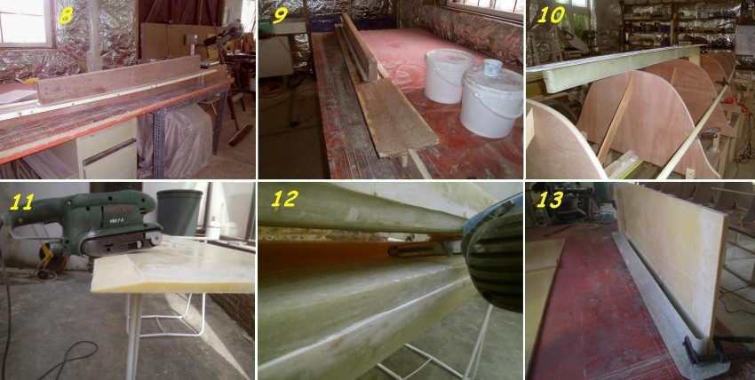
Pic-8 shows a one-piece mould being set up.
Pic-9 shows 'grout' being added forward, in order to create the bevel to match the hull bottom.
Pic-10 shows the completed fiberglass log being checked against the lower hull stations.
Pic-11 shows a centerboard case side panel being bevelled to mate with the FG log.
Pic-12 shows the recesses moulded into the log, to provide a protected location for the CB seals that are bonded in later. (The shorter quadrant CB option, does not need these recesses as seals are not required.)
Pic-13 shows a CB case panel being bonded to the exterior of the log. It's a beveled fit—like a scarf—and the interior joint then gets one layer of glass to complete the sealing. All fully detailed in the Build Manual.

In Article 4, we will start to build the main hull—using a unique combination of strip and large panels that give uncompromised underwater shape with relatively easy-to-build topsides.
See W22 Build INDEX
"Have a question or comment about the W22? If so, feel free to use our Questions & Comments Form to submit them to the designer." —webmaster
"See the Copyright Information & Legal Disclaimer page for copyright info and use of ANY part of this text or article"